While working (not so) diligently on the re-write of Holocraft I encountered a situation where the need for an age-old algorithm arose. The algorithm itself, and/or its implementation, has had many minds over the course of time to boil it down to a few bare-necessity lines of code.
 |
| Example of the problem and some possible conditions. From: http://www.owenpellegrin.com/articles/vb-net/simple-collision-detection/ |
Determining whether or not two rectangles overlap or intersect has been one of those problems that has found application in many a project. It's rather simple to implement, and most novice programmers take pride in discovering a solution to the problem, even including the case where the algorithm is extended into the 3rd dimension in the form of 'axis-aligned bounding-boxes', or 'AABBs'.
 |
| 3D axis-aligned bounding boxes intersecting. From: http://www.miguelcasillas.com/?p=30 |
There have been many games which utilize either a 2D or 3D variant of this algorithm to determine if two objects in a game world are colliding with one-another. The original Quake game is an example of a game where entities had their collision volume defined by way of an axis-aligned bounding box. This caused players to axially slide off other objects as if they were a flat cubical shape. Personally, I prefer using a cylindrical or capsule collision volume for players and NPCs, because this gives a smoother collision resolution where the player just sort of slips and slides around other players and objects. Most modern games utilize this sort of collision volume for players nowadays for low-fidelity intersection tests, and sometimes as a pre-test to avoid the cost of doing more intricate intersection tests in the case of hitscan weapons and the like.
At any rate, during my outset to re-write Holocraft it became clear that it was imperative that there be a way to detect where groove optics are overlapping, or otherwise intersecting one-another due to the fact that many of my trial-holograms thus far have been muddied in areas where the density of intersecting groove optics is too many. Too many intersections and too much overlap of grooves can completely annihilate the clarity of their reflectivity. The solution is to prevent the machining process from scribing over the same areas, allowing the fore-front optics of the hologram to take precedence over the background optics, optimizing the overall clarity of the hologram as a whole.
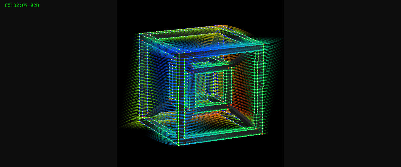 |
| A screenshot of the new Holocraft showing the geometry and optics of a moderately detailed specular hologram. As you can see it is very easy to create many overlapping and intersecting optics (the curved colored lines) which will reflect light to depict the white dots along the edges of the model's geometry. Blue optics will appear nearest, red the furthest, and green will appear with mid-range depth. |
Now, per Matt Brand's whitepaper on Specular Holography, groove optics are hyperbolas that are calculated from the assumed incident light ray altitude angle that will be illuminating the hologram. I have chosen to calculate from the the hyperbola a cubic Bezier curve, which is defined by a starting and ending point, and two control points which dictate the curvature of the line that traverses the space between the endpoints. This curve then serves as the internal representation of the base shape from which all optics for the hologram are then derived, based on the 3D position of the point that is chosen from the source hologram geometry's vertices, edges, or surfaces that will be depicted by this reflective optic.
These optic curves are segmentized by an occlusion-culling pass, which designates which spans of the curve should reflect light based on whether or not the hologram geometry should be 'blocking' their visibility, on a per-degree of viewing angle (or 'azimuth') basis.
Once these segments of visibility are determined I then need to determine which ones are intersecting or otherwise overlapping one-another too closely to cause degradation in the final hologram. One way is to brute force compare the distance of every single point of each optic segment against every single point of every other optic segment to determine if the segment needs to be clipped or split/culled, etc..
To speed this process up I have resorted to the use of a simple bounding rectangle overlap comparison. Effectively, this is a 2D axis-aligned bounding box intersection/overlap test. This is what I call an 'early out', where the core loop that is performing these comparisons and tests can quickly and cheaply pre-determine that there is no possible way for two given optic segments to be intersecting (because they are, for example, on opposite sides of the specular hologram).
If there *is* an overlap detected between the two rectangles bounding two optic segments, then Holocraft proceeds with a more detailed comparison of the two segments, effectively comparing each point on each segment with each point on the segment in question. This is a simplified explanation of the actual process which determines overlap/intersection, as the actual algorithm uses a heuristic method to dynamically adjust the increment at which it 'steps' along each segment to the next point to compare with all the points of another segment to perform a distance check. This helps to accelerate the process, which is albeit fast enough without the heuristic method being as Holocraft only performs intersection detection when the user is saving the holographic output, currently as either an SVG vector image file or directly to CNC g-code.
Now, the whole point of this blog post is to share the method by which I devised a rectangle intersection test that serves more utility for Holocraft's purposes. It would seem that with my growing years as a programmer I have been growing a rabid aversion to doing things the tried-and-true way, with a sort of desperation to find a novel way to go about doing things that people have already been doing another way for decades.
A part of the heuristic method by which Holocraft accelerates optic intersection/overlap detection relies on knowing the rectangle of overlap itself in which two given segments are possibly intersecting. Knowing that their bounding rectangles is overlapping as a mere boolean piece of information is not sufficient for it would require that *every* point on each segment is compared against *every* other point on the opposing segment. To minimize this only the points on each segment that are within the overlapping area of the rectangles is considered.
Here's a copy-pasta of what Holocraft does:
//
typedef struct
{
 float x, y;
} vec2;
//

// 2d rectangle
typedef struct
{
 vec2 min, max;
} rect2d;
//

#define MAX(a, b)  ((a) > (b) ? (a) : (b))
#define MIN(a, b)  ((a) < (b) ? (a) : (b))

// returns zero if no overlap, otherwise returns
// area of overlap and optionally the rectangle of overlap via '*o'
float intersect_rects(rect2d a, rect2d b, rect2d *o)
{
 rect2d c;
 float dx, dy;

 // find horizontal overlap
 c.min.x = MAX(a.min.x, b.min.x);
 c.max.x = MIN(a.max.x, b.max.x);

 // not overlapping horizontally...
 if((dx = c.max.x - c.min.x) < 0)
  return 0;

 // find vertical overlap
 c.min.y = MAX(a.min.y, b.min.y);
 c.max.y = MIN(a.max.y, b.max.y);

 // not overlapping vertically...
 if((dy = c.max.y - c.min.y) < 0)
  return 0;

 // caller requires rectangle of overlap ?
 if(o)
  *o = c;

 // return area..
 return dx * dy;
}
//
This is with the goal of quickly calculating the rectangle of overlap itself, while putting priority over the horizontal check over the vertical check (perhaps in Holocraft's case this should be reversed?) and will bail out if the horizontal overlap fails before bothering with the vertical overlap check.
This is in contrast to most of the functions you will find on the internet, which perform a few simple greater-than/less-than checks against the min/max of the bounding rectangles/volumes and provide no other useful information.
In the past, for game physics, I would just make everything a sphere and perform a simple pythagorean distance check against the combined radii of the two entities in question. I almost opted to use circles as early-out bounding volumes for optical segments until I actually sketched on paper how much extra space a circle would typically have over a simple bounding rectangle.
Incidentally, the rectangle boundary calculated for each segment is derived from the convex hull of each curve, which is defined by both the endpoints of the curve and the control points that define the shape of the curve itself. It is said that the entirety of a cubic Bezier curve is contained within this area, and if there was a fast way to perform intersections against these convex hulls then that is what I would do, but there really isn't. This would require a series of line intersection tests and be quite a bit more complicated than it is worth.
 |
| Demonstrating the confinement of a cubic Bezier curve to its convex-hull, as defined by its endpoints and control points. From: http://www.scratchapixel.com/lessons/advanced-rendering/bezier-curve-rendering-utah-teapot |
One of the advantages of using cubic Bezier curves as an intermediate representation is that outputting a vector image via the SVG file format allows for cubic Bezier curves to be defined as-is, without converting or transforming to any other form.
This is in contrast with outputting CNC g-code, in which machine toolpaths can only be defined as either linear or circular motions, requiring an intermediate step in Holocraft which deduces a series of circular arcs chained together to form an optic curve. This is done within a user-supplied tolerance value, to give some degree of control over how large/complex the final CNC g-code output is, and the degree to which the machined grooves are faithful to the calculated optic hyperbola.